Where do we use Viterbi Decoder ?
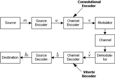
For a typical communication system shown in Figure 1, signal from the source (m) will be converted to digital form (u) by source encoder. The process here may also include redundancy removing.
Channel encoder, otherwise, adding a structured redundancy to u. A scheme called FEC (Forward Error Correction) use this redundancy to detect and correct error(s) caused by noise on the channel. Next, the resulting encoded data (v) is modulated and transmitted through the channel. During transmission it is very likely that the transmitted data is altered by noise from the channel. Therefore on the receiver side it is very likely too that the received data are not the same as the transmitted data.
It is the channel decoder duty then to reconstruct ű based on the received symbols. Because of the redundancy, it is possible that the data obtained are correct (ű=u) even though the received symbols are different from the transmitted ones.
There are two classes of FEC, one is convolutional codes, the other is block codes. The type of noise experienced on the channel determines the class of FEC used. Convolutional codes are used for channels with Additive White Gaussian Noise (AWGN) while block codes are used for channels with additive burst noise.
Viterbi Algorithm, the algorithm implemented on Viterbi Decoder, is an algorithm used to detect convolutionally encoded data. Viterbi Decoder therefore used on Channel Decoder at the receiver side when the suitable Channel Encoder, convolutional encoder in this case, used on the transmitter side.
Viterbi Algorithm
Excellent starting point to learn Viterbi Algorithm could be found on Chip Fleming's "Tutorial on Convolutional Coding with Viterbi Decoding" found in here : http://pweb.netcom.com/~chip.f/Viterbi.html or the alternate URL here : http://www.qsl.net/w3rff/viterbi/tutorial.html
Hardware Implementation of Viterbi Decoder
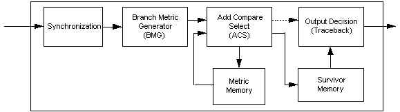
To create hardware implementation of Viterbi Decoder, basically there are 5 processes we have to do :
Therefore, a simple viterbi decoder block diagram might look like Figure 2 below.